Synchronized Clocks: Someone has to be blamed…
I blame Ariel. He took one look at the five analog wall clocks set to timezones for various offices and said “I hate that”. I looked to see why. Yes, all the second has were wildly different and the minute hands were all slightly off too. I’d been thinking about what my next electronics project would be. “How hard could this be?”
Goals
Thinking about what I’d want this to do I came up with a few goals:
- Correct and accurate time via NTP (Network Time Protocol)
- No two clocks should differ more than 100ms, they should all appear to tick at the same instant.
- Battery operation. About one year between battery changes.
- Automatic Daylight Savings Time adjustments
- Remember clock position/state on power loss
- Inexpensive – less than $20 in parts, not including the clock & batteries.
Initial Research
Started with checking if anyone had done this type of clock sync or something similar. Internet searches turned up quite a few clock projects. Many were digital and while interesting did not help much. Quite a few were complete custom clocks. I did find a few Analog Clock hacks.
I found two that were similar to what I wanted: (http://hackaday.com/2015/11/19/a-networked-analog-clock/ and https://hackaday.io/project/16742-espclock.). The problem for me was I wanted battery operation and the ESP8266 cpu/wifi module uses 70 milliamps on average – much too much for the battery powered device I wanted.
Another interesting one I found was “Crazy Clock”: (https://hackaday.io/project/5880-crazy-clock). This remained lower power but had no network connectivity to keep the clock synced with an external time source. It did however have a really nice description on how standard quartz clock movements work. And another, “Lunchtime Clock”: (http://www.instructables.com/id/Lunchtime-Clock/)). It uses a real time clock module to keep accurate track of the correct time. This one also uses too much power and does not have network connectivity.
Ticking the Clock
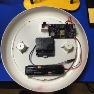
I went shopping with the wife and bought two fairly cheap ($10) analog clocks and survived “the look” when I immediately disassembled them upon arriving home.
Most quartz clock movements use a Lavet type stepping motor to physically drive the clock hands. Driving one of these requires us to alternate polarity each second. This can be done with a half H-Bridge type of circuit. I ran a number of experiments both attempting to directly drive the clock from microcontroller I/O pins and using an H-bridge type circuits. Testing driving directly meant using 3.3v or 5v depending on what micro-controller I was using at the time and I was concerned with using too much power since this was designed to be used with a 1.5v battery. I found a small low power motor controller (DRV8838) that supported motor voltages including 1.5v and decided to use that. (photo of testing operation of the DRV8838)
While testing I found that the DRV8838 does active mitigation for inductive spike coming from its load. The downside is that the DRV8838 draws more than a milliamp when enabled and when it’s disabled the active mitigation vanishes leaving you with spikes as seen here:
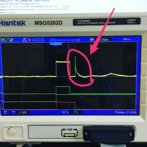
These spikes can cause tick failures and I was forced to delay disabling the DRV8838 for up to 50ms which increases the overall power usage. I actually built a few clocks using this until I realized that I could use pulse-width modulation (PWM) to control power when directly driving the motor with two of the microcontroller pins.
To drive the clock I chose an ATTiny85V. Its an 8 pin microcontroller with 8k bytes of flash, 512 bytes of RAM, 512 bytes of EEPROM and 5 I/O pins, 6 when you configure the reset pin as I/O. I used all 6 of the I/O pins: 2 to drive the clock motor, 2 for i2c communication, one for a 1Hz signal to time clock ticks, and 1 to signal a power outage so that the clock position and state can be saved.
I selected a DS3231 as a real time clock (RTC) as it is low power, has integrated temperature compensated crystal oscillator, supports a 1Hz square wave output, and has an i2c interface.
I chose an ESP8266 as the main controller to manage configuration, NTP synchronization as it’s a really cheap (less than $3) wifi module with a flash-able microcontroller and multiple I/O pins.
The way this works is that the ESP8266 wakes up at a configurable interval and makes an NTP request and computes the time offset. If the time offset is more than a threshold, and I’m using 20ms currently, the RTC is updated using a method that aligns its second boundary to where NTP says it should be. The RTC is configured to output a square wave at 1Hz with the falling edge being the second boundary. This is connected to one of the ATTiny85’s interrupt pins and configured to interrupt on the falling edge waking the the ATTiny85 from sleep to tick the clock each second.
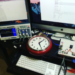
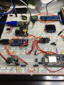
I assembled the version using the DRV8838 on a solderless breadboard for testing and initial software development. In this early version I was using an Arduino Nano in place of the ATTiny85 for convenience.
Software Design
The three main components, an ESP8266, a DS3231, and an ATTiny85 are interconnected with a two wire protocol called i2c. The ESP8266 is the bus master and both the DS3231 and ATTiny85 are configured as slave devices.
When the ESP8266 starts, and this could be from a cold start like a power fail or a wakeup from its deep sleep mode, it attempts to connect to wifi. If it fails, or was never configured, it creates a captive WiFi portal that allows configuration of WiFi SSID and password, current clock position, NTP server, time change information, and some advanced settings that tune the parameters used to drive the clock motor.
After connecting to WiFI it makes an NTP request and computes both the time offset and network delay as described in section 8 of the NTP RFC. The offset is used to adjust the RTC only if the offset is greater than a threshold and if the network delay is within 1 standard deviation from the last 7 or 8 requests. The last 8 offsets that were used to adjust the RTC are saved and used to compute the drift in parts per million of the RTC. This is used between NTP requests to help keep the RTC and the clock, ticking at the correct time.
Next the current time is read from the RTC and converted to a clock position. Since most analog clocks only have a 12 hour face there are only 43200 possible unique hand positions so we represent the position of the analog clock as an unsigned integer between 0, midnight/noon, and 43199, 11:59:59/23:59:59. The current clock position is also read from the ATTiny85 and an adjustment is computed and sent back to the ATTiny85.
The ESP8266 then enters its lowest power sleep mode, deep sleep, where only a wakeup timer and the 512 bytes of memory that we use to store the NTP samples are powered.
Setting the RTC within milliseconds is a challenge since it keeps time only at a one second granularity. The key is that when you write the seconds value to the RTC it synchronizes its 1Hz square wave output to that moment. The specific verbiage in the DS3231 data sheet is “The 1Hz square-wave output, if enabled, transitions high 500ms after the seconds data transfer, provided the oscillator is already running. This makes the falling edge the start of each second. So by using the offset from NTP and coordinating when to set the time to be where NTP says the second should start syncs the RTC within a few milliseconds.
The other RTC trick is that when we read the time for the origin timestamp of an NTP request we wait for the falling edge of the square wave first. Since this is a second boundary the NTP timestamp will be with zero fraction value.
One area that’s still a work in progress is deciding how long to wait between NTP polls. The longer this is the less overall power will be used and the longer the batteries will last. Currently, and this is a work in progress, I’m using samples obtained since the previous adjustment to compute an estimated drift. This is then used to compute how long at the estimated drift rate it would take the clock to drift by the offset threshold. (Actually testing shows that less than 20% of the power usage is caused by NTP polls, so I’ll probably disable this feature and opt for a regular poll schedule based on the DS3231’s ±2ppm accuracy specification.)
The ATTiny85 is interrupt driven and when not servicing an interrupt it’s kept in one of two low power states. Most of the time it’s in the “power down” state where it uses the least amount of power. It it is woken with either an interrupt from the falling edge of the 1Hz signal from the RTC, by an i2c “start condition”, or lastly by a power fail interrupt.
On each falling edge of the 1Hz signal the ATTiny85 will execute an interrupt service routine that will start a tick on the clock. This is performed by configuring one of the timers to send a 4khz signal for a short duration to one of the two pins used to drive the clock. The exact pin alternates each second so that we are properly alternating the polarity to drive the clock motor. The duty cycle and duration of this is configurable allowing adjustments for different clock motors, different clock hand sizes, etc. While the PWM timing is active the ATTiny85 uses ‘idle’ sleeps between PWM interrupts to reduce power usage.
A start condition indicates that the ESP8266 is attempting to communicate and the ATTiny85 will use “idle” sleeps until the command has been received then executed in an interrupt service routine. When it’s complete the ATTiny85 returns to power-down. Typical commands are reading the current clock position and sending an adjustment, or possibly sending new tick duration or duty cycle values. When any value has been updated it it saved to EEPROM so settings will survive power outages.
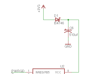
Power failure is signaled by the voltage regulator when it can no longer maintain its output at the correct voltage. This signal will interrupt the ATTiny85 causing it to finish any in-process tick and then save the current clock position in EEPROM. When power is restored it can immediately resume ticking without waiting for commands from the ESP8266. To maintain power long enough to accomplish this I used a large capacitor, isolated by a diode on the power (VCC) pin of the ATTiny85. The diode insures that the ATTiny85 is the only device powered from the capacitor.
Power Management
All of the main components have some form of low power mode that I’m using to reduce power usage.
The ESP8266 has “Deep Sleep that allows it to use approximately 20 micro-amps. Deep sleep timer only lets you sleep for just over an hour at a time so I keep track of how much mode sleeping is needed and set deep sleep to wake without the radio turned on, saving power, if mode sleep is needed. During these intermediate wake-ups I apply drift compensation if its been computed.
- Deep sleep: ~20 uA
- Radio off: ~15 mA
- Radio on: ~ 80mA
The ATTiny85 has a “power down” mode where interrupts will wake it back up. Its woken on the falling edge of the 1Hz signal from the RTC and powers back down after the tick has been completed. An “idle” mode is also used during the “tick” processing where timer interrupts are used to wake from idle.
- Power down: 0.2mA
- Idle: 0.8 mA
- Awake: 3mA
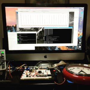
I measured the overall power usage and found the following: (these were measured before I added hourly drift compensation)
- NTP Request: 70 mA for 10 seconds
- Hourly Wakeup between NTP requests 21 mA for 1 second
- normal ticking: 0.28 mA
Measurements were taken with an INA219 current sensor module attached to a Raspberry PI and graphed using gluplot:
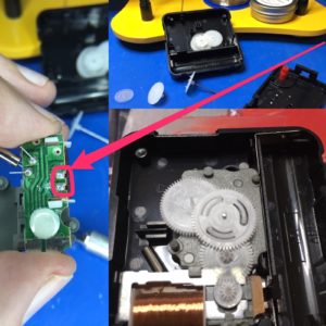
Clock Modification
In order to drive the clock we have to solder a pair of wires to the clock’s motor. I usually use a sharp knife and cut any traces on the clocks original PCP that connect to the motor as well.
Configuration
When the clock is initially powered on it creates a wifi captive portal. It will show up in the list of available wifi networks as SynchroClockXXXXXXX (where the X’s are some number). When you connect to this you are given a menu that lets you set many configuration options:
- Wifi Network (SSID).
- Wifi Network password.
- Clock Position – enter the current time shown on the clock as HH:MM:SS (note that the clock is always stopped when the config portal is up and it should display the correct hand position.)
- NTP Server to use for time synchronization.
- 1st time change as 5 fields (US/Pacific would be: 2 0 0 3 2 -25200 meaning the second Sunday in March at 2am we change to UTC-7 hours).
- occurrence – ‘2’ would be the second occurrence of the day of the week specified, ‘-1’ would be the last one.
- day of week – where ‘0’ = Sunday.
- day offset – needed for “the friday before the last sunday of the month”, this would be occurrence = -1, day of week=0, day offset = -2
- month – where ‘1’ = January.
- hour – where ‘0’ = midnight.
- time offset – this is the offset in seconds from UTC.
- 2nd time change as 5 fields as described above (US/Pacific: 1 0 0 11 2 -28800 meaning the first Sunday in November at 2am we change to UTC-8 hours).
Advanced options:
- Stay Awake – when set true the ESP8266 will not use deep sleep and will run a small web servers allowing various operations to be performed with an http interface. (I use this to test new clock timings)
- Tick Pulse – this is the duration in milliseconds of the “tick”.
- Adjust Pulse – this is the duration in milliseconds of the “tick” used to advance the clock rapidly.
- Adjust Delay – this is the delay in milliseconds between “ticks” when advancing the clock rapidly.
- Network Logger Host – (optional) hostname to send log lines to.
- Network Logger Port – (optional) tcp port to send log lines to.
- Clear NTP Persist – when set true clears any saved adjustments and drift calculations.
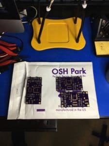
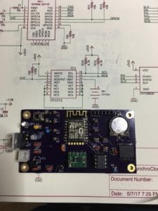
PCB Design
I designed a simple PCB available from OSH Park.
Source Code and Design Files
All source code and design files are located in a GitHub repository: https://github.com/liebman/AnalogClock.
Future Ideas
- Li-ion battery & charging
- Solar or other energy scavenging technique
- Support 16 HZ “non-ticking” or “silent” clocks